|
|
|
Home
|
What
follows in Exhibit C. is
relevant to the opposing patent’s claim 1. The combination of these
prior art disclosures incorporated in Exhibit
C., render the opposing patent’s claim 1 obvious as well.
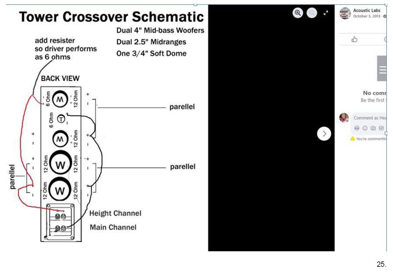
What follows on
page 25 in
this chart is Heather’s October 3, 2013 Facebook published post from
her publicly accessible Acoustic Labs company facebook page, her
“Tower Crossover Schematic”, notably illustrated and labeled a back
view of the speaker Referring to the detailed notes that follow in
reference to Heather’s prior art publication on page 25
disclosed is, most all of the opposing claim 1’s elements.
OPPOSING
CLAIM ELEMENTS IN BOLD BLACK
”a crossover circuit for use
in a speaker system”- The prior art on page 25
titled: "Tower Crossover Schematic" - Illustration: Shows a 4" mid-bass woofer (W) and a 2 1/2"
midrange (M) speaker connected to a terminal panel receiving a height
channel signal. The signal is routed shown by the red line to both the
mid-bass woofer (W) and the midrange (M) speaker. The title explicitly
identifies the component as a "crossover". The routing of a
single height channel/signal to both a mid-bass woofer (W) and a
midrange (M) speaker demonstrates the function of a crossover network in
a speaker system – dividing the height channel/signal signal and
directing it to different drivers. This constitutes an explicit
disclosure of a crossover for use in a speaker system
” transmiting sound waves”- The prior art
on
page 25
titled “Tower crossover Schematic” disclosing the drawing of a speaker with input terminals for a height channel/signal
(and also a main channel), attached to the speaker; signals are routed
to a 4" mid-bass woofer (W) and a 2 1/2" midrange (M) driver.
A speaker with input terminals, a woofer (W), and a midrange (M) driver
is inherently designed to transmit sound waves by converting electrical
signals into mechanical vibrations. The functionality of the speaker
system (routing signals to components) explicitly implies the
transmission of sound.
”for
a full-bandwidth”-
The
prior art on page 25 titled
“Tower crossover Schematic” discloses the presence of the woofer (W) (4" mid-bass) and midrange (M) (2
1/2") driver, designated to the height channel/signal, inherently
implies their function of transmitting sound waves within their
respective frequency ranges. A person skilled in the art would
understand that the combination of these drivers, managed by a
crossover, aims to reproduce a portion of or the full audible spectrum
depending on the specific speaker design. The diagram depicts the
speaker with the woofer (W) and midrange (M) driver utilized with the
height channel/signal. While
"transmits sound waves for a full bandwidth" might not be
explicitly stated, the use of speaker drivers (woofer and midrange),
coupled with a crossover to direct the appropriate frequency ranges to
each inherently discloses the transmission of sound waves across a
broader spectrum. The presence of both a mid-bass woofers (W) and a
midrange (M) driver implies the system is designed to handle a
significant range of frequencies, encompassing what is often referred to
as "full bandwidth" in the context of a speaker system (a
full-bandwidth can be a height channel/signal and the combination of a
height channel/signal and a main channel/signal which is also explicitly
disclosed).
”object
based audio content”- The prior art on page 25
titled
“Tower crossover Schematic discloses a drawing of a crossover schematic of a speaker - Separate inputs for height
channel and main channel labeled on the terminal panel - Routing from
the height channel input to a 4" mid-bass woofer (W) and a 2
1/2" higher frequencies midrange (M) driver for the height channel
- Routing from the main channel input to 4" mid-bass woofers (W)
and 2 1/2" higher frequencies drivers for the main channel. While
not explicitly stating "object audio based content," the
disclosed speaker design, with its dedicated height and main channels
and their respective components and inputs, inherently supports the
processing and reproduction of object-based audio content that utilizes
these channels (like Dolby Atmos) to create an immersive 3D sound
experience. A skilled artisan would recognize that the illustrated
speaker is capable of handling the separate audio streams and positional
metadata associated with object-based audio.
”having
height and direct components to be reflected off an upper surface of a
listening environment”- The prior art on page 25 titled “Tower Crossover Schematic” shows a speaker with terminal inputs for both a
height channel/signal and a main channel/signal. A red line from the
height channel input leads to both a 4" mid-bass woofer (W) and a 2
1/2" midrange (M) driver, both initially depicted as direct-firing
in the primary illustration. Heather’s
other prior art in this same Exhibit C. pages 26-44 relevant to the Acoustic Labs published Tower
Crossover Schematic on
page 25
explicitly discloses that the 2 1/2" driver is angled upward, thereby
resulting in reflection off an upper surface of a listening environment
for the height channel/signal, having height and direct components to be
reflected of an upper surface of the listening environment for a height
channel/signal. While the illustration
on page 25
may initially seem to depict only direct-firing drivers, the
presence of dedicated height channel inputs, combined with
the
explicit disclosure in the other prior art in Exhibit C. pages 26-44
relevant to the Acoustic Labs published Crossover Schematic on page 25 disclose that the 2 1/2" driver at the top
is angled upward for the height channel resulting in reflection, disclosing
the "height and direct components to be reflected off an upper
surface of a listening environment" element
which is indeed present in Heather’s prior art.
A person of ordinary skill in the art, considering the
disclosures in Exhibit C.,
would understand that the height channel signal is directed both
directly and through reflection off the upper surface of the listening
environment.
The Tower Crossover
Schematic on page 25
shows a speaker tower with a woofer and a midrange/high-frequency
driver. All the other prior art in Exhibit C. shows the speaker with the exact same components, dual
(two) 4” mid-bass woofers, dual (two) 2 ½” midranges (mid-high
drivers) and, one soft dome tweeter. with an angled driver configuration. A person of ordinary skill in the
art (PHOSITA) would have been motivated to combine the Tower Crossover
Schematic on page 25
with the angled driver configuration of the other prior art references
for the speaker in Exhibit C. page
26-44 in this
chart. The woofer is shown as direct-firing in the Tower Crossover
Schematic on page 25. This feature is present in both references and is a known
element in the art. The combination is motivated by the desire to
achieve improved height channel effects, as explicitly taught and
illustrated in other references in this Exhibit
C. pages
26-44.
The Tower Schematic on page 25
shows a direct-firing midrange driver. The other prior art in this Exhibit C. pages
26-44 explicitly describes and
illustrates the 2 ½” driver at the top of the Tower Crossover
Schematic on page 25
is angled upward for a height channel. The modification of
angling the driver from the Tower Crossover Schematic on page 25
is a straightforward application of the known technique in the other
prior art in this Exhibit C
pages
26-44 to
achieve a predictable acoustic result, consistent with the Supreme
Court's reasoning in KSR.
The combination is a matter of routine design choice for a PHOSITA
seeking to improve the perceived height of the sound.
“an
interface from a renderer to a speaker”-
The terminal panel is illustrated on the speaker Tower Crossover
Schematic on page 25.
The terminal panel is the interface. The diagram explicitly shows inputs
on the terminal panel labeled which come from the audio source receiver.
Based on the doctrine of inherency, a PHOSITA would understand that the
terminal panel's sole function is to receive signals from a source
component like a receiver. The receiver acts as the "renderer"
by providing the processed height and main channel signals to the
speaker. The red line on the schematic, labeled as the height channel
input. The schematic explicitly shows the input for the height channel.
The black line on the schematic, labeled as the main channel input. The
schematic explicitly shows the input for the main channel
”having a direct firing driver within a cabinet and oriented to
transmit sound along a horizontal axis substantially perpendicular to a
front surface of the cabinet an upward-firing driver oriented at an
inclination angle between 18 to 22 degrees relative to the horizontal
axis”- The
prior art on page 25 titled “Tower crossover Schematic” explicitly
illustrates the direct-firing woofers within the cabinet, oriented to
fire horizontally and substantially perpendicular to the front surface
designated to a height channel (and a main channel). The drawing which
is a back view of the speaker cabinet illustrates a signal from both a
height channel and a front main channel directed to the direct firing
woofer (W) to direct sound horizontally. The Tower Crossover Schematic
explicitly shows a mid-high midrange driver designated to the height
channel, separate from the main channel drivers indicated with the red
line from the terminal panel of the height channel/signal Heather’s other prior art in this same
Exhibit
C. relevant to the Acoustic Labs published Tower Crossover Schematic on page 25 explicitly discloses that the 2 1/2" driver
is angled upward,
a
PHOSITA would have been motivated to combine
the Acoustic Labs Prior Art disclosure in Exhibit
C. in this chart to the Acoustic Labs Tower Crossover Schematic on page 25
in this chart utilizing the same channels a front main and height
channel with the other Prior Art in Exhibit C page
26-44 in this chart’s explicit
disclosure that the same driver is "angled upward." The
selection of an angle, such as 18-22 degrees, is a predictable and
routine optimization for achieving a specific acoustic effect. A PHOSITA,
through routine experimentation, would arrive at an effective upward
angle for sound projection to a listener's ceiling, with 18-22 degrees
falling within the range of predictable solutions.
“and a
separation circuit comprising a crossover stage having a low-pass
section configured to transmit low frequency signals below a threshold
frequency to the direct-firing driver, and a high-pass section
configured to transmit high frequency signals above the threshold
frequency to the
upward-firing drive”- The prior art on page 25 the "Tower Crossover Schematic" explicitly indicates a
"separation circuit." The "Tower Crossover
Schematic" shows a line from the terminal input for the height
channel/signal to a 4" mid-bass woofer (W) and the line then routed
to a 2 1/2" midrange (M) driver. Heather’s other
prior art disclosures in this Exhibit C. pages 26-44 relevant to the Acoustic Labs published Tower Crossover Schematic on page 25 explicitly disclose that the 2 1/2" driver at the top for the height
channel is angled upward.
The combination of the "crossover schematic" on page 25 showing a "separation circuit" connected
to a 4" mid-bass woofer (W) (direct-firing) and a
2 1/2" driver (upward-firing as disclosed in separate prior art in
this Exhibit C. pages 26-44)
demonstrates the function of the low-pass and high-pass sections.
The separation circuit naturally implies frequency filtering to direct
the appropriate frequency ranges to the corresponding 4” mid-bass
woofer (W) and the 2 1/2” (M) midrange driver also disclosed as a
mid-high driver in the other prior art disclosures in this Exhibit
C. The use of the terms "mid-bass woofer"(W) and
"midrange" (M) (and “mid-high in other prior art in Exhibit
C.), for the 2 ½ ” driver further supports the intention of
separating low and high frequencies. The Tower Crossover Schematic on page 25 explicitly discloses the separation circuit and a
low-pass section configured to transmit low frequency signals below a
threshold frequency to the 4” direct-firing woofer for a height
channel, and a high-pass section configured to transmit high frequency
signals above the threshold frequency to direct-firing 2 ½” driver
for the height channel. A
person of ordinary skill in the art (PHOSITA) would have been motivated
to combine the Tower Crossover Schematic on page 25
with the angled driver
configuration of the other prior art references for the speaker in Exhibit C page
26-44t. The
woofer is shown as direct-firing in the Tower Crossover Schematic on page 25 This feature is present in
both references and is a known element in the art. The combination is
motivated by the desire to achieve improved height channel effects, as
explicitly taught and illustrated in other references in this Exhibit
C. pages
26-44.
The other prior art in this Exhibit
C explicitly pages
26-44 describes
and illustrates a midrange mid-high driver angled upward for a height
channel. The modification of angling the driver from the Tower Crossover
Schematic on page 25 is a
straightforward application of the known technique in the other prior
art in this Exhibit C.
pages
26-44 to
achieve a predictable acoustic result, consistent with the Supreme
Court's reasoning in KSR.
The combination is a matter of routine design choice for a PHOSITA
seeking to improve the perceived height of the sound
published 10-3-
2013, the link for Heather’s Acoustic Labs prior art “Tower
Crossover Schematic” link can be copied and pasted into browser
https://www.facebook.com/photo/?fbid=693577577342016&set=pb.100063888528735.-2207520000
|
|
|
|